The Empenage (Page 1 of 3)
Journal Cover Page Page 2 Page 3
(To navigate the photo journal, click on the tabs on the right and the links at the top or bottom of this page.)
Horizontal Stabilizer |
|
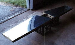
| Here, the rear spar of the horizontal stabilizer is assembled and primed. The prepped, but unprimed, aft ribs lay on the work bench next to the spar. | 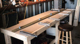 |
| The horizontal stabilizer skeleton is in the jig which keeps it straight and true during fitting and drilling of the skins. Otherwise, the flight surface might develop a twist adversely affecting the planes flight characteristics. The skeleton is made up of the front and rear spars and the fore and aft ribs. | 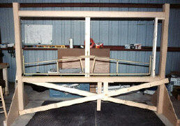 |
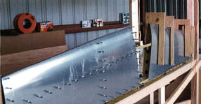 |
Giant homemade clothespins help hold the skins in place while I drill them to the skeleton. Then, "cleco" clamps inserted in the drilled rivet holes keep from moving during the drilling process. The position of a plumb bob hanging in the reference plane relative to the center line drawn on the front spar provides assurance that the stabilizer remains true. |
| It's a lot easier to rivet the skin onto the skeleton with the help of a friend. Here, Chuck Johnson(#1 helper) holds the bucking bar inside the stabilizer with one hand. The forward ribs have been removed to allow access. We riveted the rest of the skin using the "peel back" method in which one of us peels the skin back from the corner and shoots the rivets with the pneumatic rivet gun while the other contorts arm and wrist to reach the back of the rivets with the bucking bar. | 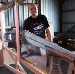 |
 |
Here's the riveted horizontal stabilizer waiting to be primed. It needs the fiberglass tips and elevators. But, first we have to make the vertical stabilizer. |
Vertical Stabilizer |
|
| Just as for the horizontal stabilizer the fabrication of the vertical stabilizer starts with the spar and ribs to form the skeleton. Then, the skin is riveted to the skeleton. Here, the skeleton is fixed to the jig and the skin is clecoed in place after drilling the rivet holes. | 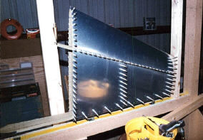 |
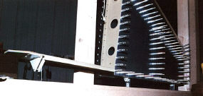 |
This shot shows how the stabilizers were bolted to the horizontal member of the jig through the control surface attach brackets. I made some supports out of steel strapping material and screwed them to the jig in the exact locations. |
| This time Buzz and Chip VanPatton helped rivet the skin to the stabilizer. We set it aside and start work on the rudder. | 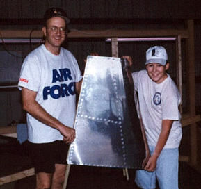 |