The Empenage (Page 2 of 3)
Journal Cover Page Page 1 Page 3
(To navigate the photo journal, click on the tabs on the right and the links at the top or bottom of this page.)
Rudder |
|
 |
The first step in building the control surfaces is to lay out the locations for the stiffeners on the inside of the skin. |
| Then, the stiffeners are cut to the appropriate length with aviation snips from thin aluminum angle. Both the left (red handle) and right (green handle) snips are shown. The stiffeners also get a taper that will follow the taper of the finished rudder. | 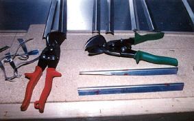 |
| Here is a picture of a finished rudder stiffener. | 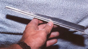 |
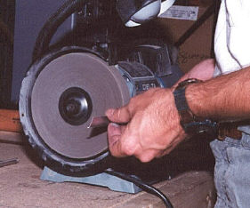 |
And, as with all the metal parts, machined edges must be polished to remove all nicks an scratches so they will not become stress points susceptible to cracking later. |
| Now, the stiffeners can be drilled to the rudder skin. I used scrape of 1/4" plywood on top of the table as a backing. The drill goes through stiffener and skin and into the plywood making a hole for the cleco clamp which holds the parts firmly together as the drilling progresses. Once drilling is complete, the parts are detached and all holes deburred. Then, the holes are dimpled in preparation for flush rivets. | 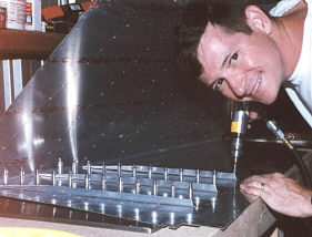 |
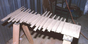 |
Some finishing nails into my saw horses serve as anchors for the stiffeners keeping them from being blown around in the primer spray. |
| To prep the parts for priming, I first wetted the aluminum with a deck sprayer and scuffed the surface with a maroon ScotchBrite® pad. Next, with a sponge and Simple Green® I washed off any dirt and aluminum particles created by scuffing. The final step is to degrease the surface by wiping it with an acetone soaked paper towel. |  |
 |
Here, the inside of the rudder skin is primed and ready stiffener riveting. |
 |
The protective plastic that was removed from the inside before priming is now removed from the outside surface of the skin before riveting. Most of the parts come with this covering to protect them from corrosion until I can get them primed. I like to leave it on as long as possible. |
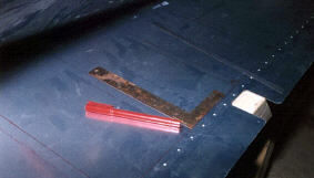
| To prepare for back-riveting on the stiffeners, I first insert a rivet into each hole. You can just see the edge of the 1/4" thick, steel back-riveting plate against which the rivets will be formed. | 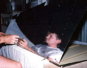 |
| Riveting tape is applied to keep the rivets in place until they can be formed. Yes, I have already riveted on the stiffeners on the other side of the rudder skin using all the same steps. |  |
 |
Here you can just see the rivets sticking up through skin waiting for a stiffener to be slipped over them. Once in place, the back-rivet set on the pneumatic riveting gun forms the rivet's shop head. You can't see it here, but that back-riveting plate is under the skin providing a hard smooth backing for the manufactured head as the rivet is formed. |
| WOW! Beautiful rivets without any visible marks, dings, or scratches. | 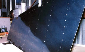 |
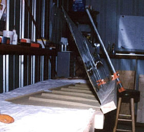 |
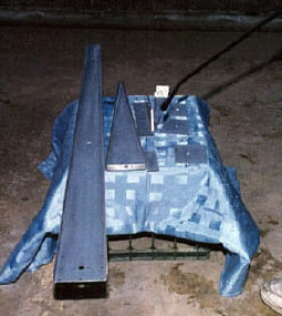
Now that the stiffeners are riveted into place, I can finish bending the rudder's trailing edge. I made a simple bending brake with a six-foot long 2"x8" cut in half and rejoined with door hinges. The bottom half is secured to the work bench so that its edge is flush with the work bench's top surface. The final touch is a pipe clamp that provides enough leverage to crunch down on the rudder's trailing edge. |
| Just a little more crunching and it will be ready to insert into the jig and receive the skeleton. |  |
| But first, we need to make the skeleton. I have drilled all the parts for rivets according to the plans and am now scuffing with the ScotchBrite® pad in preparation for priming. | 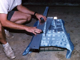 |
 |
In this picture, you can see the working end of the deck sprayer as I rinse skeleton parts before washing with Simple Green® and rinsing again. |
| After degreasing with acetone, I mixed up the two part Dupont Variprime® and sprayed it with a touch up spray gun. All the aluminum parts get this treatment. | 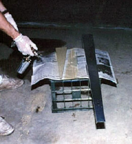 |
| The trickiest part of making the rudder skeleton is definitely the control horn and its support bracket. There is going to be a rivet where each cleco is located. The silver colored clecos clamp through holes for 3/32"diameter rivets and the copper colored ones are for 1/8" rivets. | 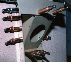 |
 |
Here is the rudder riveting jig used to keep the rudder straight and true while the skin is riveted to the skeleton. I leveled the table and screwed the jig down to it along some measured, perpendicular lines. |
 |
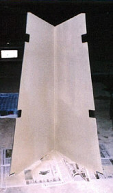
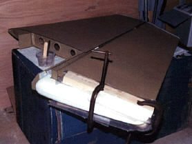
Its a rudder seen from the bottom. The fiberglass bottom will cover this area. The grey color is a self etching primer from a spray can. I use it on smaller parts to keep from having to mix up the other kind and then spend the time cleaning the spray gun. I'll show you the technique for bending the leading edge in the elevator portion of the photo journal. |
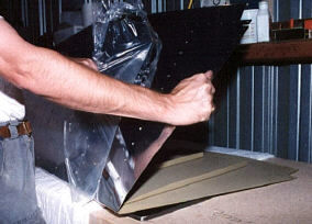
| The fiberglass tips are attached to both the rudder and vertical stabilizer with a marine epoxy and resin mixture. This picture also shows the rudder fitted to the vertical stabilizer at the hinge points. Good news! It fits perfectly! |  |
 |
The rudder bottom is attached with epoxy as well. But it takes some trimming to clear the control horn. Later, I'll work on this some more to fill in the open areas with foam board and cover and fair it with epoxy and resin. |