The Empenage (Page 3 of 3)
Journal Cover Page Page 1 Page 2
(To navigate the photo journal, click on the tabs on the right and the links at the top or bottom of this page.)
Elevators |
|
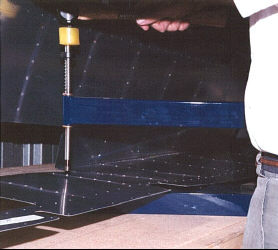 |
I used a riveting arbor with dimple dies installed to dimple all the skins. This is the left elevator skin. It lies inside the arbor with the male die protruding through a rivet hole. When the hammer strikes the plunger, it drives the female die onto male die sandwiching the skin in between and forming a dimple, around the rivet hole. This dimple allows the rivet to be driven flush with the surface of the skin. |
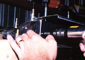
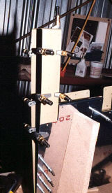
| The spars of all the empenage control surfaces (rudder & elevators) have reinforcement plates around the rod end bearings that will hold the control surfaces to the stabilizers and provide pivot points. In this picture, I'm drilling the reinforcement plates to the elevator spars. | 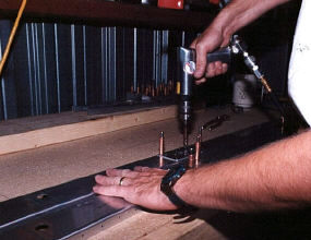 |
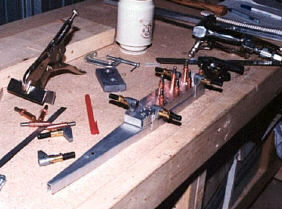
| Whenever dimples in rivet holes are needed near the edge, we can use the hand squeezer. This device uses the same dimple dies, but is a little quicker and more convenient than the arbor. The holes being dimpled here are along the flange of the spar that has already been drilled to the elevator skin. |  |
 |
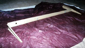
Here is the counterbalance arm under construction. It will attach to the outboard end of the elevator. Later, I will install some precast lead weights in its forward end that will help to keep the elevators in trail when they are installed on the horizontal stabilizer. If you look closely, you can see an example of a technique used to keep the flanges lined up with each other so the skin will lie flat. Small scraps of aluminum are clamped to the flanges with cleco edge clamps. The scraps simulate a skin that will later stretch across the two flanges. |
| The counterbalance arm and the inboard rib are clamped to the spar for a test fit. | 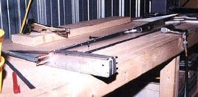 |
 |
We want the skeleton to be lined up perfectly with the edges of the skin. So, it's necessary to clamp it inside the skin while drilling the inboard rib to the spar. |
 |
After riveting the skeleton together, it is prepped and then gets a coat of primer. |
| The next step is to fit the steel control horn to the skeleton. Once I'm satisfied that it is clamped in exact position the plans require, I'll drill it to the skeleton. |  |
 |
As with the rudder, once the inside of the skin is primed and the skeleton constructed, it's time to for the final test fit in the elevator assembly jig. |
| Here is a little trick discovered by some builder's and subsequently included in the manufacturer's instructions. The silicone sealant/adhesive is applied across the stiffeners at the trailing edge of the control surfaces. | 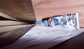 |
 |
The idea is to dampen the vibrations at the trailing end of the stiffeners that might cause cracks to form in the trailing edges of the control surfaces. |
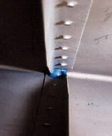
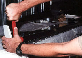
| Satisfied that everything lines up as it should, the riveting begins on the right elevator. A standard riveting procedure is to have a cleco or a rivet in the holes on either side of the holes currently being riveted. |  |
| Here is the left elevator in the riveting process. The missing section is a cut out for the elevator trim tab. | 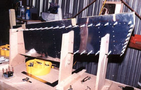 |
 |
Here is a close up of the counter balance arm with its forward skin section ready to be drilled to it's flanges./B> |
| This elevator trim motor mounting plate comes precut and bent to shape. But, the builder has to prep and prime it and then attach the plate nuts. | 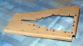 |
| The plate goes on the inside of the left elevator skin around the access hole. Here, you can see the plate nuts on the inside of the plate. | 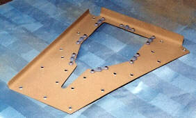 |
 |
Here is the electric elevator trim servo motor mounted to the access plate that will screw into the mounting plates. The copper colored clecos temporarily hold it together while I make sure the control rod has adequate clearance. |
| Now, with the access plate screwed in place and the servo motor installed, you can see the control arm protrude from the under side of the left elevator. Next, we need to fabricate and install the trim tab. | 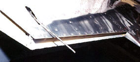 |
 |
This shot looks down on the top side of the elevator. You have to look closely, but you should be able to make out half of the trim tab attach piano hinge riveted to the elevator. |
| With clecos holding the other half of the piano hinge to the trim tab, the tab can be test fitted to the elevator. |  |
 |
Back on the underside again, you can see the trim motor access plate and the trim tab in its final assembled state. The control rod was cut and fitted so the tab is in the neutral position. |
| One of those motivational moments when I had the chance to hold a significant component at an advanced stage of completion. | 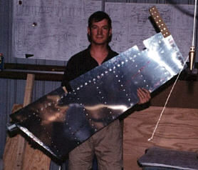 |
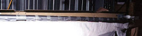 |
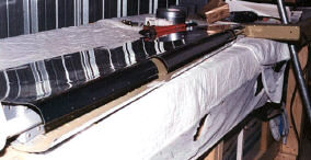
The next few pictures show the process for bending the leading edge of the empenage control surfaces. |
| First, a steel water pipe from one of my pipe clamps is duct taped to one side of the leading edge. Then, I used a pipe wrench to rotate the pipe bending the skin in a gentle curve. | 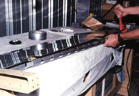 |
| With the pipe removed and the elevator flipped over, you can see the bent edge. | 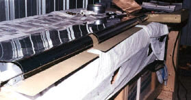 |
 |
Next, the other side is bent in the same way. |
 |
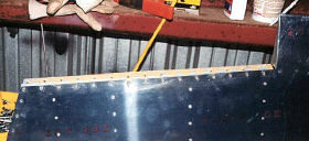
This is about the best you can do using the pipes. Now comes the hard part, bending the edges by hand until they come together. The problem is that the edges are pretty sharp and each side is in the way of bending the other. |
| Once satisfied with the fit, it gets clecoed together and then blind riveted with a pop rivet puller. After, the elevator leading edges came out a lot better than the rudder, I went back and reworked the rudder leading edge by drilling out some of the pop rivets and manhandling the edges until they fit together better. These seams aren't structurally important and they aren't very visible, but I would always know it wasn't as good as it could be and it didn't take too much time to fix. | 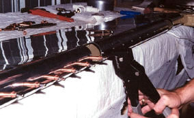 |
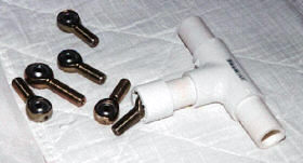 |
These are the rod end bearings that hold the rudder and elevators to the stabilizers. They thread into some plate nuts that have been riveted to the stabilizer spars. Because the plate nuts are designed not to let the rod end bearings turn, the bearings are hard to install by hand. The solution is to make an installation tool. I made mine out of some PVC parts as described on Sam Buchanon's builder's web site. (Thanks Sam) |
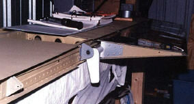
| Now it's time to do a little sub assembly. With the horizontal stabilizer laying on the work bench and one elevator installed, the builder has to drill a mounting hole in the control horn. To get it in exactly the right place, the control horn mounting bearing on the stabilizer is used as a drill guide. As per the instructions, I found some brass tubing, at a local hobby shop, with an inside diameter the same size as my drill bit and an outer diameter the same size as the inner diameter of the bearing. | 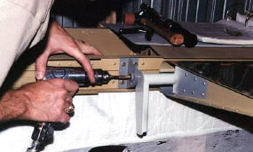 |
 |
|
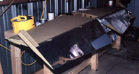 |
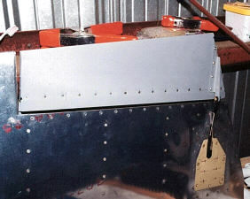
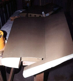
Here is a picture of the elevators fitted to the stabilizer before the counter balance weights or fiberglass tips are installed. |
| After a lot of fitting and filing, I used an epoxy resin mixture with a bonding filler from West Marine® to attach the fiberglass tips to the elevators and stabilizer. The counter weights have already been install in the counter balance arm. I had to add a little extra lead weight to the precast ones to make it balance right. | 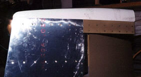 |
| Here is the first real fiberglass work to be done on the RV-6A. The builder has to close in the leading edge of the counter balance arm. One option is to bond in some foam and cover it with fiberglass cloth and epoxy. Later, I'll add some more epoxy with a light fairing filler to better shape this surface. | 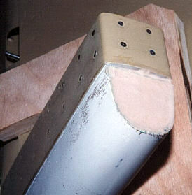 |
 |
Presenting, one horizontal stabilizer with elevators! The elevators are weighted to allow for the final paint. Once painted, the lead weights accessible on the inboard side of the counter balance arm can be drilled out until the elevators balance in the trail position, line up with the chord line of the stabilizer. |